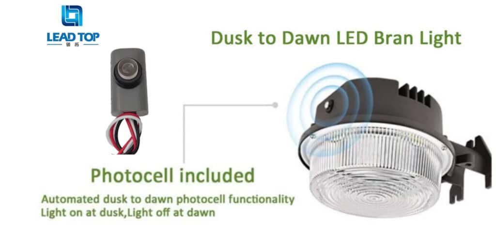
Outdoor illumination systems depend deeply on automatic control devices to safeguard dependable dusk-to-dawn operation. One of the most extensively used devices for this purpose is the thermal фотоэлемент, a sensor that robotically switches illumination fittings on at night-time and off during the day. Thermal photocells have been used for years in street illumination, commercial illumination, and security illumination due to their long-lasting structure and steady performance.
Though, as illumination technology changes from old-style lamps to еnergy-efficient LED modules, new compatibility attentions have emerged. One problem that many installers and illumination engineers encounter is related to the minimum load requirement of thermal photocells.
In certain installations, users report that the photocell does not switch properly, sparks during operation, or fails to turn on small LED fittings. In numerous circumstances, the reason is not a faulty photocell but rather a incongruity between the photocell’s switching characteristics and the electrical load connected to it.
What Is Minimum Load?
Minimum load denotes to the lowermost electrical power level mandatory for a switching device to function dependably and constantly.
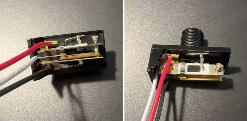
Thermal photocells work using a mechanical switching mechanism that depends on heat and physical movement. The internal components typically include:
- A light sensor that senses surrounding glare
- A small internal heater that triggers the switching process
- A bimetal strip mechanism that opens or closes electrical contacts
When environmental light drops underneath the stated lux level, the photocell initiates the internal heater. The heater warms the bimetal strip, causing it to bend and close the electrical contacts. When the contacts close, power flows to the lighting load.
For this process to work smoothly, the electrical load connected to the photocell must fall within a certain working range. If the load is too small, the switching behavior may become unsteady.
Why Does Minimum Load Matter in LED Applications?
Customary outdoor illumination systems mainly used incandescent or high-intensity discharge (HID) lamps. These illumination types normally consumed significant power. A single lamp often ranged from 60 watts to 200 watts or more, providing a large and steady electrical load.
Current LED illumination systems are very different. Advances in proficiency permit LED modules to generate the same glare while consuming a smaller amount of energy. Several LED fittings may function at only:
- 10 watts
- 15 watts
- 20 watts
Whereas this energy proficiency is advantageous for decreasing electricity usage, it can introduce compatibility contests for mechanical switching devices like thermal photocells.
When the load becomes tremendously small, the photocell may face problems upholding steady switching behavior.
Several common indications associated with low-load conditions comprise:
- Late switching reaction
- Failure to latch the contacts properly
- Recurrent trembling during operation
- Erratic ON/OFF cycling
How LED Drivers Affect Load Behavior?
One more factor that obscures minimum load requirements in LED illumination systems is the existence of LED drivers.
Dissimilar to customary incandescent lamps, which behave as simple resistive loads, LED fittings comprise electronic driver circuits that control power before transporting it to the LED chips.
These drivers comprise numerous internal components intended to calm voltage and decrease electrical intrusion. Typical driver components comprise:
- Rectifiers
- Input capacitors
- Electromagnetic interference (EMI) filters
- Power conversion circuits
When the attached LED load is very small, these electrical characteristics may stop the thermal photocell from facing the steady circumstances it was made to function with.
Consequently, the switching mechanism may behave incompatibly.
What Is Considered a Safe Load Range?
Although minimum load specifications vary contingent on the producer and product model, numerous thermal photocells function most dependably when the illumination load surpasses a certain threshold.
In numerous real-world installations, steady performance is attained when the attached load is about:
20 to 30 watts or higher.
This range offers adequate electrical circumstances for the photocell’s mechanical switching system to work smoothly.
Other aspects also effect performance, comprising:
- The LED driver’s inrush current characteristics
- The photocell’s contact rating
- The existence of zero-cross switching technology
In these cases, an electronic photocell may offer improved compatibility because electronic switching circuits can work efficiently with smaller current levels.
How to Avoid Low-Load Problems?

Evading compatibility problems among photocells and LED illumination systems needs watchful planning and system assessment.
Some practical steps can benefit to confirm steady operation.
The first thing is to check the wattage of the LED illumination module. Understanding the power usage of the fitting permits installers to decide whether it covers the photocell’s suggested load range.
Next, it is significant to review the LED driver’s technical specifications, particularly the inrush current characteristics. Certain drivers produce large current thwarts that may effect switching behavior.
One more worthwhile strategy is choosing the suitable photocell technology. For modest or high wattage loads, тепловые фотоэлементы normally perform well. For very low-power LED modules, electronic photocells may offer more steady switching.
Lastly, performing system-level testing before extensive installation is highly suggested. Testing permits engineers to perceive actual working situations and pinpoint potential compatibility problems timely.
Table 1: Comparison of Traditional Lighting Loads and LED Loads
| Особенность | Traditional Lamps (Incandescent/HID) | LED Lighting Systems |
| Typical Power Consumption | 60W – 200W+ | 10W – 50W common |
| Electrical Load Type | Resistive | Electronic driver load |
| Startup Behavior | Smooth current increase | Capacitor charging surge |
| Compatibility with Thermal Photocell | Очень высокий | Depends on load size |
| Minimum Load Concern | Rarely an issue | Often important |
Table 2: Photocell Selection Based on LED Load Size
| LED Fixture Power | Рекомендуемый тип фотоэлемента | Причина |
| Below 20W | Электронный фотоэлемент | Handles low steady current better |
| 20W – 50W | Тепловой или электронный | Both types may perform well |
| Above 50W | Термофотоэлемент | Strong switching stability |
| Multiple fixtures combined | Thermal photocell or zero-cross version | Improved durability for larger loads |
Заключение
The minimum load requirement is an imperative but repeatedly unnoticed factor when fitting thermal photocells in current LED illumination systems.
Thermal photocells depend on mechanical switching mechanisms that do best when attached to loads within a particular electrical range. As LED fittings become more and more energy proficient and function at lower wattages, compatibility between photocells and illumination loads must be cautiously assessed.
By understanding load characteristics, revising LED driver specifications, choosing suitable photocell technologies, and performing system-level testing, illumination experts can guarantee steady dusk-to-dawn control.
With more than 10 years of experience in photo control manufacturing, Lead-Top Electrical Co., Ltd. offers licensed wire-in, НЕМА twist-lock, and Zhaga series photocell solutions made to support dependable performance in contemporary LED illumination applications international.