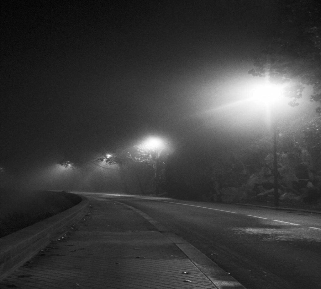
As LED illumination technology continues to swap old-style lamps in street illumination, commercial buildings, and outdoor structure, the interface between illumination control components and LED drivers has become a significant technical consideration. While thermal fotocellen have long been used for automatic dusk-to-dawn illumination control, some users notice that these devices do not always work properly with certain LED light engine modules.
In a lot of cases, the problem is generally related to electrical compatibility between the thermal photocell and the LED driver circuitry. LED drivers act very differently from old illumination loads, which can sometimes generate switching challenges.

How Do Incandescent Lamps and LED Loads Behave Differently?
There are many reasons, one of which is that incandescent lamps and LED modules act differently. Old-style incandescent lamps are resistive loads, when voltage is applied, electrical current flows through the filament uninterruptedly. This produces heat and light. The current increases slowly and remains steady during operation. Because of this anticipated behavior, most switching devices, containing thermal photocells, can easily control incandescent lamps without difficulty.
LED light engine modules, on the other hand, are far more multifaceted. A typical LED illumination system commonly includes some electronic components that control electrical power before it reaches the LED chips.
A standard LED light engine module typically contains:
- An LED board or COB (Chip-on-Board) module
- A constant-current LED driver
- Rectifier circuits
- EMI (electromagnetic interference) filters
- Capacitors and other power-conditioning components
These electronic elements convert the entering AC power into the steady DC current required by LEDs. Because this process includes electronic switching circuits and energy storage components such as capacitors, the electrical behavior of LED drivers during startup and closure is very different from that of old-style lamps.
When power is applied, LED drivers often draw a brief but high surge of current, known as inrush current, which charges internal capacitors promptly. This electrical behavior can sometimes interact with the switching mechanism inside a thermal photocell.
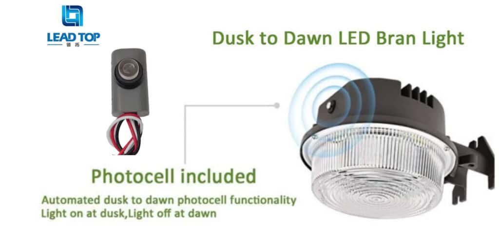
How Does a Thermal Photocell Operate?
A thermal photocell is a simple yet dependable automatic illumination control device that reacts to surrounding light levels. The internal design typically contains a light sensor, a small heater element, and a bimetal strip switching mechanism. The working process can be defined in numerous steps.
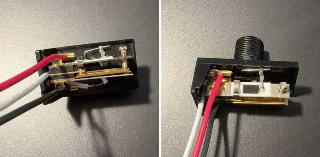
First, the photocell monitors the nearby light level constantly with light-sensitive sensor. When the surrounding lighting drops, normally around sunset, the internal heater starts. The heater turns off when surrounding light increases, and the bimetal strip cools; it goes back to its original position, opening the electrical contact. Thus, cutting off the power supply and turning the light off.
This thermal switching mechanism offers several advantages.
Thermal photocells are known for:
- Durable tolerance to electrical outpourings
- Simple mechanical construction
- Verlengde levensduur
- Steady performance in outdoor environs
Why Can Low-Wattage LED Loads Affect Thermal Photocell Operation?
One of the most common reasons thermal photocells may not function properly with some LED modules is very low load wattage.
In old-style illumination systems, lamps usually consumed reasonably high amounts of power. Street lamps and commercial fixtures often used 100W, 250W, or even higher wattage lamps, which generated steady electrical loads for switching devices.
Numerous contemporary LED modules, however, are made to work at much lower power levels, sometimes as low as 10–20 watts. When the attached load is very small, the electrical switching characteristics of the system may become less steady.
Thermal photocells normally work more dependably when the attached load surpasses a certain minimum level. In many real-world installations, a minimum load of approximately 20–30 watts is suggested to guarantee steady switching performance.
How Does Inrush Current from LED Drivers Affect Photocell Performance?
When an LED driver is first connected to power, the internal capacitors must charge promptly. During this transitory charging process, the driver may draw a large surge current that lasts only a fraction of a second. Even though short, this outpouring can be considerably higher than the normal functional current of the LED system.
When a thermal photocell closes its electrical contacts to turn on the illumination fixture, this abrupt inrush current flows through the photocell contacts. In certain cases, this electrical surge can create short-term uncertainty in the switching mechanism.
Probable effects comprise:
- Flickering when the light first turns on
- Delayed startup of the LED module
- Electrical stress on switching contacts
One solution to lessen this problem is the use of zero-cross switching technology. A zero-cross photocell stimulates the electrical circuit exactly when the AC voltage waveform crosses zero volts. Switching at this point considerably decreases electrical stress because the sudden voltage and current are nominal.
Why Can Capacitive Leakage Cause LED Modules to Glow Slightly?
A third compatibility problem that may appear when using thermal photocells with LED modules is capacitive leakage current.
Many LED drivers contain EMI filter capacitors that help decrease electromagnetic intrusion in electrical systems. These capacitors are attached within the driver’s input circuit and can permit a very small amount of current to pass even when the main power circuit is technically open.
When a photocell switches off the illumination circuit, this small leak current may still run through the driver’s capacitors. Though the current is very small, some highly competent LED modules can respond to it.
This can cause negligible effects such as:
- A pale luminosity from the LED module when the light is supposed to be off
- Incomplete shutdown rather than complete dark
Are Thermal Photocells Suitable Only for Incandescent Lighting?
Several urban illumination projects effectively use thermal photocells with LED fixtures. Though, because LED drivers vary considerably between producers, compatibility testing is always suggested during system design.
Different LED drivers may have different characteristics such as:
- Startup current levels
- Internal capacitor sizes
- Power factor correction circuits
- EMI filtering structures
Table 1: Key Differences of Incandescent and LED Lighting Loads
| Functie | Incandescent Lamp | LED Light Engine Module |
| Electrical Load Type | Resistive load | Electronic load |
| Startup Current | Gradual increase | Hoge inschakelstroom |
| Internal Electronics | Geen | Driver, rectifier, capacitors |
| Compatibility with Switches | Zeer hoog | Depends on driver design |
| Sensitivity to Leakage Current | Zeer laag | Higher sensitivity |
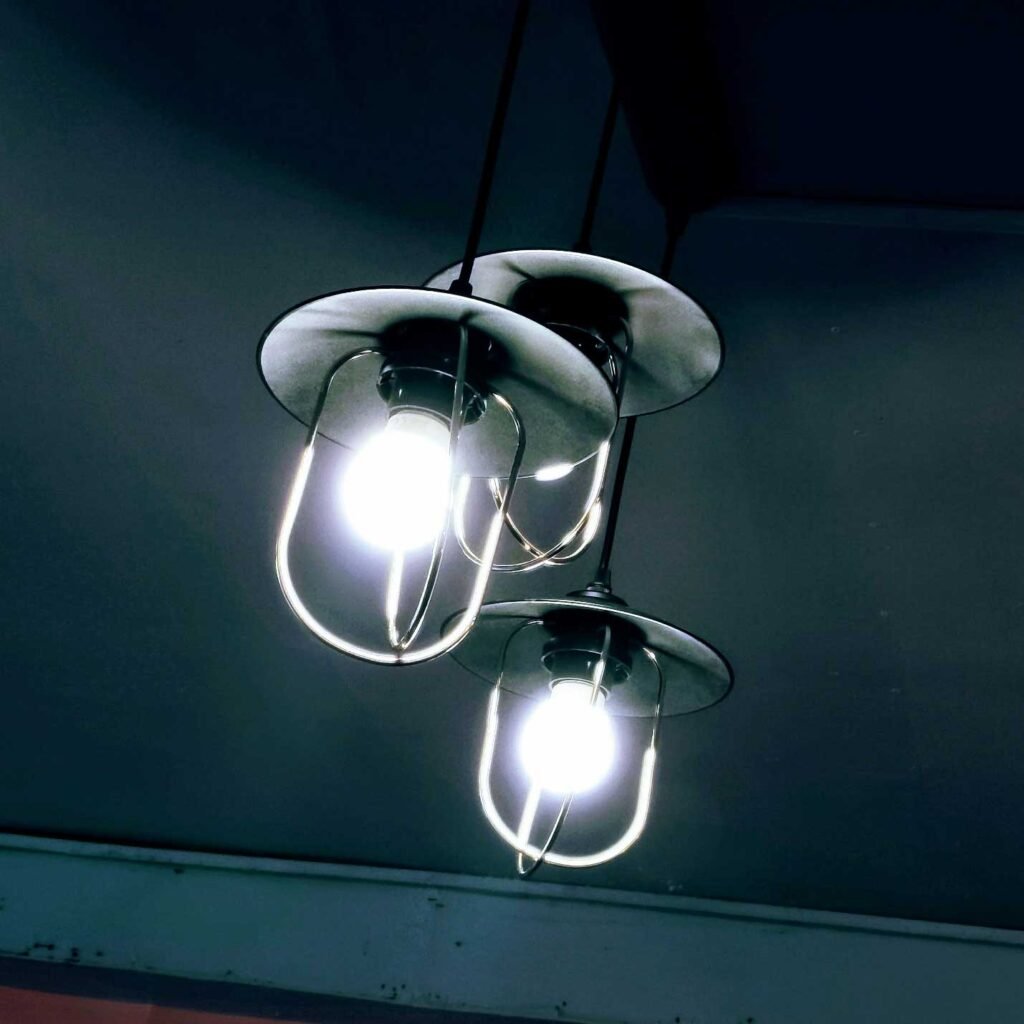
Table 2: Common Causes of Photocell and LED Compatibility Issues
| Probleem | Technische oorzaak | Possible Solution |
| Flickering at startup | High inrush current from LED driver | Use zero-cross switching photocell |
| LED does not start | Load wattage too low | Ensure minimum load requirement |
| Faint glowing when off | Capacitive leakage through EMI filters | Use driver with improved isolation |
| Unstable switching | Driver electrical characteristics | Perform compatibility testing |
Conclusie
Thermal photocells continue to be a dependable yet extensively used solution for automatic outdoor illumination control. Their simple mechanical design with high surge forbearance and verified resilience makes them perfect for applications such as street illumination, parking areas, and commercial outdoor fixtures.
Still, contemporary LED light engine modules use electronic drivers, which behave differently from old-style incandescent loads. Factors such as low load wattage with high inrush current and capacitive leakage can occasionally form compatibility challenges between LED drivers and thermal photocells.
By carefully assessing driver specifications and switching methods, engineers and installers get to choose the most appropriate photocell configuration. With proper system matching and compatibility testing, steady dusk-to-dawn control can be attained in contemporary LED illumination systems, guaranteeing proficient and dependable outdoor lighting.