In modern lighting systems, the integration of light controller sockets plays a vital role in automating indoor and outdoor lighting based on ambient light levels. This comprehensive guide is designed to explain in detail how to wire a light switch socket, provide insight into the process, and highlight best practices for optimal performance
Definition: What is photocell socket?
The photocell socket is a specialized intermediary device designed to connect photocells and lighting fixtures. It serves as a crucial component in lighting systems by providing a physical interface, facilitating the connection and signal transmission. This functionality enables effective communication between the photocell and the lighting fixture, enabling intelligent and automated lighting control.
Types for photocell receptacle
Photocell receptacle are mainly divided into two categories: one is the NEMA standard receptacle, including 3-pin, 5-pin, and 7-pin sockets. The other category is Zhaga receptacles, which are 4-pin sockets.
Wiring steps
Safety Precautions:
Prioritize safety before commencing any wiring project. Ensure the power is turned off, use insulated tools, and wear appropriate protective gear. Additionally, if necessary, consider collaborating with a licensed electrician.
Tools and Materials:
Gather the necessary tools, such as wire strippers, pliers, and screwdrivers, along with the recommended wiring materials, bulbs, ballast or driver. Choosing high-quality materials ensures a reliable and durable installation.
Identify the wires:
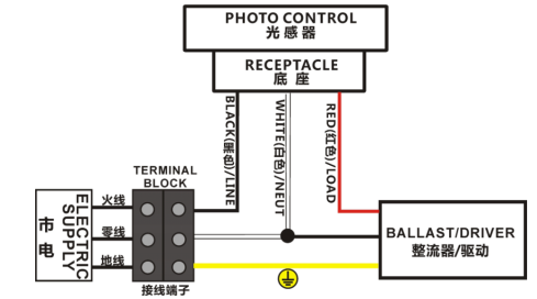
Understanding the color-coded wires is crucial. Typically, black represents the line (live) wire, white denotes the load (neutral) wire, and red indicates the load wire.
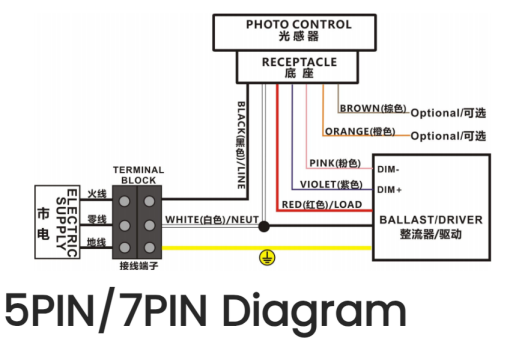
Brown Wire/Pink Wire/ Orange Wire/Purple Wire are dimming wire.
Red Wire: Load Line
Connect the red wire to the ballast or driver in the lighting system.
White Wire: Neutral line
The white wire is split into two by wire connectors, with one end connected to the neutral wire of the power system, and the other end linked to the driver or ballast.
Black Wire: Live line
The black wire can serve as an additional live wire or for specific applications based on your electrical system. Connect it accordingly.
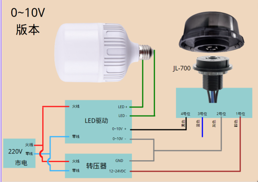
Brown Wire/Pink Wire/ Orange Wire/Purple Wire: dimming line(0-10V Dimming & Dali Dimming)
Dimming line is mainly used to connnect the DIM- & DIM+on the ballast and driver.
Prepare the photocell socket:
Inspect the photocell socket and become familiar with its components. Securely install the socket in a position where it can effectively sense changes in ambient light.
Connection procedure:
Follow the manufacturer’s instructions to connect the load, line, and neutral. Ensure that cable connections are secure, using cable connectors or terminals to enhance safety.
Photocell Wiring Diagram:

(Only two dimming wires will be used, not four at the same time. Two wires are connected to 0-10V dimming, and two wires are Dali dimmable)

4 pin Zhaga Socket

Testing Installation:
After completing the wiring, use a multimeter to verify the connections. Test the functionality of the photocell socket by exposing it to different lighting conditions, ensuring that the connected lighting fixtures respond appropriately.
Troubleshooting Tips:
Common issues may include loose connections, incorrect wiring, or sensor malfunctions. Systematically troubleshoot to identify and address the problems.
Wiring Precautions:
Kindly be advised that for the proper installation of a photocell controller receptacle, it is imperative to strictly adhere to the provided operating instructions and comply with the local electrical codes. This ensures not only the effective functioning of the device but also promotes safety and compliance with established standards. Please follow the guidelines meticulously to guarantee a secure and efficient integration of the photocell controller into your lighting system.


