A good photo switch sensor that is badly mounted will still fail the luminaire in the field. The sensor reads the sky through a cover that may block it. The receptacle sits on a housing surface that may not seal. The wiring nobody routed during design gets crammed in at final assembly.
Most photocell content is written from the control side:
- Spanning
- Laden
- Surge
This article explores light photocell sensor integration from the luminaire design perspective. It covers:
- Twist-lock vs. wire-in controls
- ANSI C136.10 and C136.41 receptacle mounting
- Internal space
- Bedrading
- Pre-production checklist

Why Should Lighting Control Integration Be Considered During Luminaire Design?
The cost asymmetry is the main reason.
- Before tooling
Adding a receptacle pocket to a die-cast housing is a drawing change.
- After tooling
It is a tool modification, a seal redesign, and a requalification of the luminaire’s IP rating.
Retrofit photocontrol receptacles exist, such as lamp-post mounted or wire-in piggyback types. They further enhance protection of already IP-geclassificeerd housing by adding:
- An extra enclosure
- An extra cable entry
- Extra failure points to a luminaire
Design-stage integration protects three things at once:
- The luminaire’s ingress protection
- The sensor’s view of the sky
- The serviceability of both
For OEMs, there is a market reason too. Photo sensor compatibility is increasingly a tender requirement ("NEMA receptacle ready" or "Zhaga ready"). Designing the interface early widens the addressable market without changing the optics.
Should You Choose Twist-Lock or Wire-In?
Each route has structural consequences.
Draaivergrendeling route
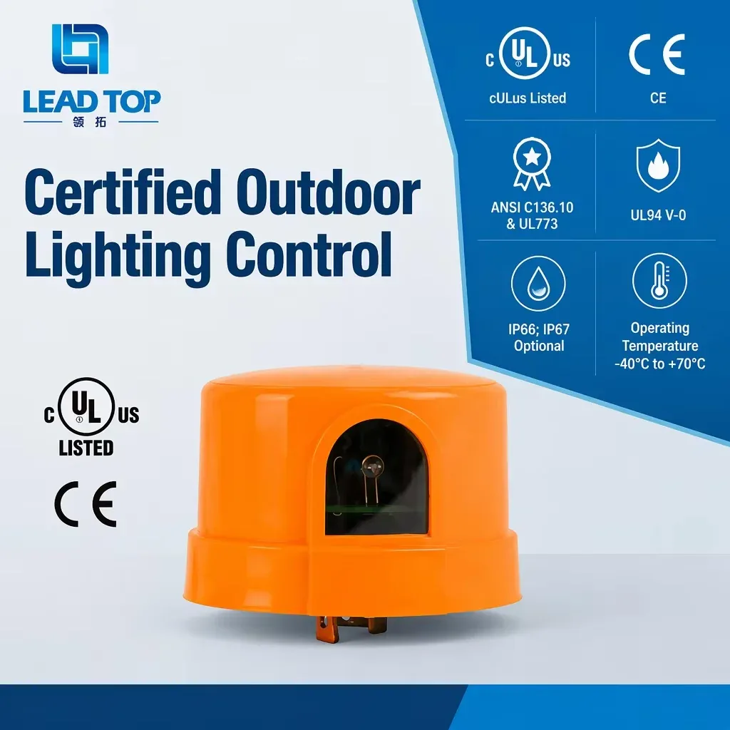
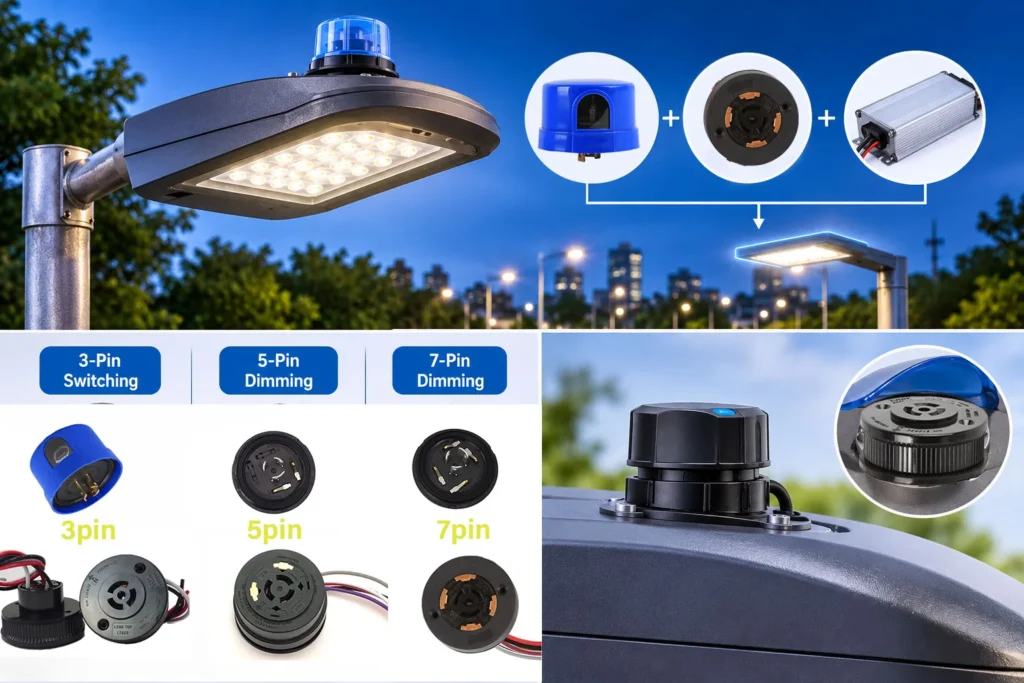
The luminaire carries a receptacle on the housing top. This could be:
- ANSI C136.10 3-pin for switching
- ANSI C136.41 5-pin or 7-pin for dimming
For the control and its cover, the housing needs to accept the:
- Receptacle body and fasteners
- A gasketed interface
- Vertical clearance
Wire-in route
The control is wired inside the luminaire. You need internal volume for the control body, a way to absorb its fixed leads with proper strain relief, and a sensor window or position with sky view.
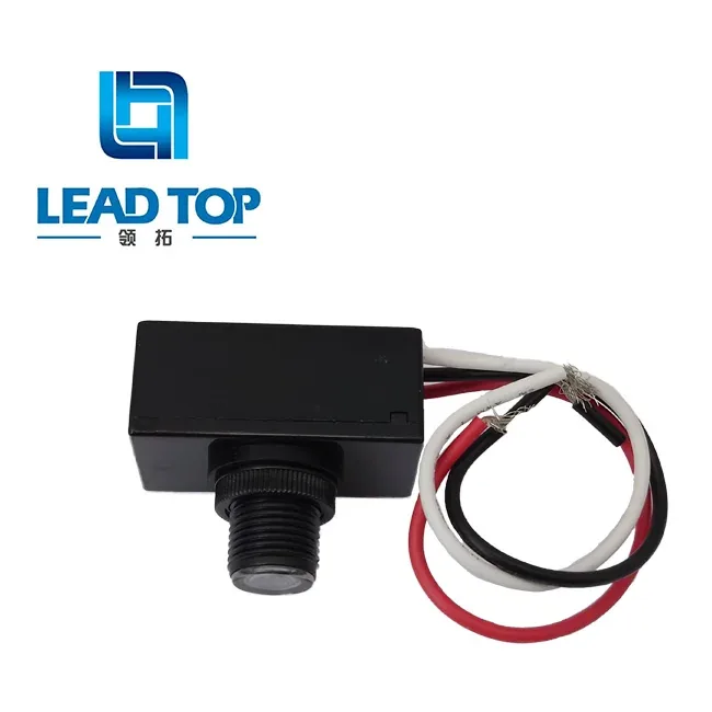
Note: The LT310A ships with UL1015 18AWG leads, 16 cm long.
| Factor | Twist-lock + receptacle | Wire-in control |
| Field replacement | Photocell swaps quickly, no tools | Requires opening the luminaire |
| Housing change | Receptacle pocket and gasketed top | Internal volume and sensor window |
| IP responsibility | Seal at the receptacle interface | Seal at the housing or sensor entry |
| Inventory logic | Luminaire ships without control; control added per market | Control fixed at production |
Vuistregel
Twist-lock suits products sold into several markets or markets with NEMA norms. Wire-in suits designs where the control is specified once, and the housing can’t host a top-mounted receptacle, such as compact floodlights and solar integrations.
How Should You Plan NEMA Receptacle Mounting?
Position and levelness
Positie
Mount the receptacle on the upper surface. A vertical face or a spot under an overhang permanently degrades the sensor’s sky view.
Levelness
The sensor reads horizontal light. A tilted mounting surface adds a constant offset to the turn-on point. Keep the plane within the tilt the photocell switch datasheet tolerates, and remember that pole or arm installation adds tilt on top.
What should the housing drawing include?
- Aperture and hole pattern per ANSI C136.10 or C136.41. Confirm against the receptacle’s dimensioned drawing before tooling. Don’t scale from photos.
- A flat, machined gasket seat. The LT605 family uses a silicone gasket, and the housing must compress it uniformly, so surface waviness matters.
- Fastener bosses sized for the receptacle screws, placed so the cover clears the housing in every orientation.
- Clearance above the receptacle for the photocell body plus the tallest cover, past brackets, surge devices, and signage.
Why is cover height a design input?
The LT100C cover comes in 90, 100, and 130 mm heights (C3090, C3100, C3130). A taller cover shields the sensor from oblique light, such as approaching headlights or reflective facades. But it can clip the sky view under a close overhang. Choose the height against the housing geometry, not the price list.
What Space and Wiring Does the Luminaire Need?
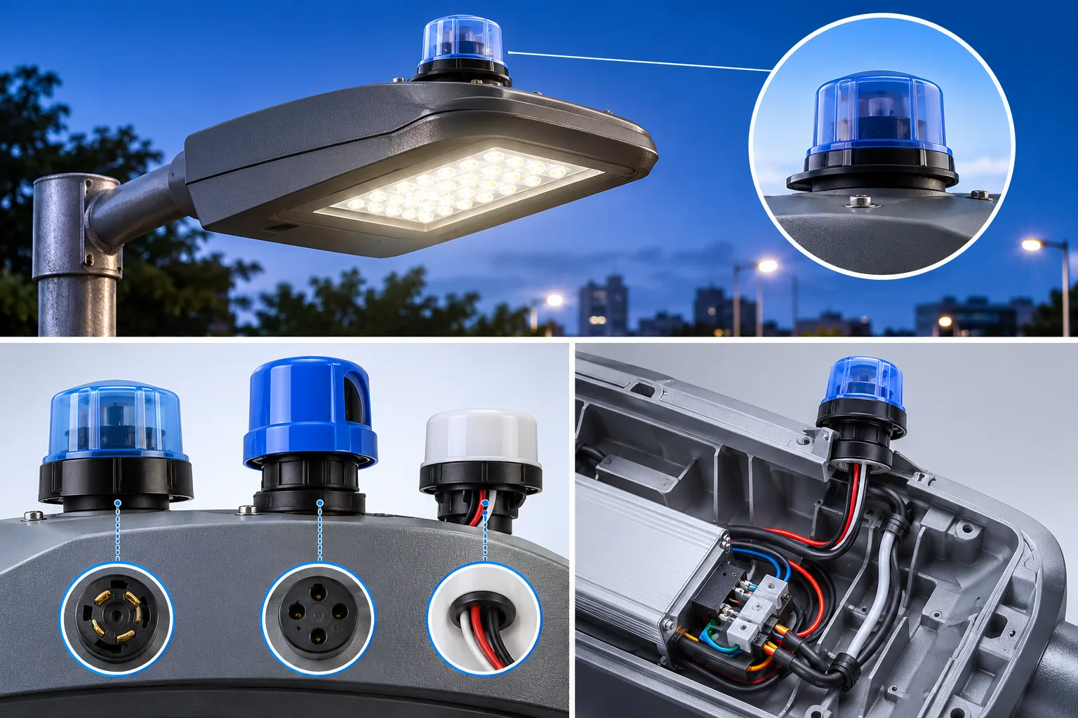
Driver layout
Leave service slack between the receptacle leads and the driver terminals. The LT605 family ships with UL1015 105°C / 600V wire, so route it away from heat-sink hot spots and respect the 105°C ceiling.
Signal versus power
C136.41 signal contacts are rated 30V / 0.25A (phosphor bronze, gold-plated). Keep signal leads away from noisy power runs, and cross them at right angles where they must meet.
Strain relief
Every wire that terminates at the receptacle needs an anchor inside the housing, so servicing the photocell doesn’t tug the driver terminals.
Maintenance envelope
The point of a twist-lock interface is a quick swap. If a technician must remove a bracket or driver cover to reach the photocell sensor, the design has cancelled its own benefit. Check the swap path in CAD before tooling.
Wire-in variant
Reserve volume for the control body and its 16 cm leads, with strain relief at both ends. For tight interiors, the LT310LE mini (300W / 300VA, LED 2A) is intended for compact builds.
How Do You Design for Fixed and Rotatable Receptacles?
| Model | Structuur | Design consequence |
| LT605 | Vast | Simplest, lowest profile. The housing drawing fixes the sensor’s facing |
| LT605R | Draaibaar | Body rotates to align the sensor after mounting; one tool serves several arm or pole orientations |
| LT635 | 360° zonder gereedschap | Orientation corrected in seconds with no tools, by installers or maintenance teams |
Which one fits your housing?
- Fixed arm geometry, factory-controlled assembly: the LT605 NEMA-fotocelhouder is enough and keeps the housing top clean.
- One housing, several mounting variants (different arm angles, wall brackets, mid-pole): specify a rotatable receptacle in the tooling so one casting covers the family.
- Installers set the final facing, or crews re-aim on live streets: the LT635 fits.
Rotatable bodies can be slightly larger in diameter. Verify the pocket diameter and cover clearance against the rotatable drawing, not the fixed one. For the full comparison, see our LT605 vs LT605R vs LT635 guide.
What Should a Pre-Tooling Checklist Include?
| Rekening | Wat te bevestigen | Against what |
| Interface standard | C136.10 (switching) or C136.41 (dimming), 3/5/7-pin | Project control spec |
| Spanning en belasting | Receptacle contacts 480V / 15A; control voltage covers the driver input range | Control and receptacle datasheets |
| Dimming path | 0–10V or DALI driver; signal pins 30V / 0.25A | Driver datasheet |
| Isolatie | 3,000V test (C136.41 family) | Receptacle test report |
| Afdichten | Gasket material and seat geometry; IP target for the assembled luminaire | Housing drawing and gasket spec |
| Sensor geometry | Cover height (90/100/130 mm), sky view, tilt tolerance | Housing CAD |
| Temperatuur | −40°C to +70°C applies to the assembled pocket, not only the lamp compartment | Thermal simulation or test |
| Service path | Photocell swappable without removing other parts | Assembly CAD |
| Zhaga variant (LT600) | 4-pin (24VDC / DALI± / IO), IP66, IK09, aluminium mounting ring; 10kV to the mounting surface is insulation withstand, not a surge rating | Zhaga Book 18 and LT600 drawing |
These numbers are interface-level. Final compatibility is between the specific photocell model and the specific driver, so confirm the pair, not the categories.
How Does Lead-Top Support Luminaire Manufacturers?
The support is interface engineering. Lead-Top does not design luminaires. It offers four things:
Drawings first
Dimensioned drawings for the LT605 family, LT100B/LT100C, and LT600, before quotes.
Design review
Send the luminaire drawing and pocket proposal, and the team checks receptacle fit, cover height against sky view, and sealing geometry.
Sample pairs
Matched automatic light sensor and receptacle samples for your own IP and cycle testing, with the pairing confirmed on the actual driver.
Production alignment
Fixed or rotatable selection, colour and cover options matched to your SKU plan.
Which products suit which design situation?
| Luminaire design situation | Products to integrate |
| Switching interface (3-pin) | LT110 / LT124L photocells + C136.10 receptacle family |
| Dimming interface (5/7-pin) | C136.41 dimming photocontrols + LT605 / LT605R / LT635 |
| One casting, many orientations | LT605R or LT635 |
| No top-mount pocket (compact, solar) | LT310A wire-in family; LT310LE mini for tight builds |
| Zhaga-ready housing | LT600 receptacle + LT6001 controller (0–10V) |
Veelgestelde vragen
Where should the photocell receptacle be mounted on a street light?
On the housing’s upper surface, with the sensor facing the sky and the plane as level as the datasheet’s tilt tolerance allows. A vertical face or a spot under an overhang degrades the sensor’s view and can cause late turn-on.
What hole and mounting pattern does a NEMA dimming receptacle need?
ANSI C136.10 and C136.41 define the interface, but make tooling from the receptacle’s dimensioned drawing, not the standard alone. Request the LT605 / LT605R / LT635 drawings before cutting the die.
Which cover height should we design around: 90, 100, or 130 mm?
Match the cover to the housing geometry. Taller covers shield the sensor from oblique sources. Shorter ones suit tight overhead clearance. Decide against the CAD.
Do we need a rotatable receptacle for different arm angles?
If one housing serves multiple mounting orientations, yes. The LT605R or tool-free LT635 lets the installer align the sensor after mounting. A fixed LT605 assumes the factory controls the final facing.
We can’t put a receptacle on top. Can we still use a photocell?
Yes, with a wire-in control such as the LT310A family. Plan internal volume for the body and its 16 cm leads, or consider the LT310LE mini for compact housings. The sensor still needs sky view.
What should we send before finalising tooling?
The luminaire drawing with the proposed pocket location, the driver datasheet (voltage, dimming protocol, inrush), and your target markets. Lead-Top can then return a receptacle and photocell pairing with drawings and matched samples before the tool is cut.
Laatste woorden
Plan photocell integration during the CAD stage by confirming receptacle position, gasket design, wiring, and mounting orientation. Share your luminaire drawing and driver datasheet with Lood-Top for a compatibility and fit review. The team will recommend a matched photocell and receptacle combination and provide samples for IP and cycle testing.


 English
 Portuguese (Brazil)
 Spanish
 Russian
 Dutch
 Japanese
 Portuguese (Portugal)