A photocell sensor, also called a dusk-to-dawn switch, is a smart device controlling outdoor lighting controllers by switching lights on/off at dusk and dawn, This mechanization increases energy and guarantees consistent lighting, Whether you’re installing a twist-lock photocell or a direct wire-in photocell, understanding the correct wiring diagram and installation process is critical for safety and reliable operation.
Photocell Wiring Basics
Standard 3-Wire Wiring
Most wire-in photocell sensors used in residential and commercial outdoor lighting presents a 3-wire configuration. Below is a standard color code reference:
| Wire Color | Function | Connects To |
| Black | Line (Hot/Live) | Power Source (L) |
| White | Neutral (N) | Power Source (N) |
| Red | Load (Switched) | Light Fixture |
- Black (Line): Connects to the incoming hot/live power supply.
- White (Neutral): Connects to the neutral wire of the power supply.
- Red (Load): Connects to the live input of the light fixture. This wire is switched on or off depending on ambient light.
This wiring allows the photocell sensor to control the light fixture automatically.
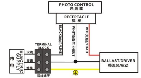
Wiring Diagram
Here’s a wiring diagram for a 3-wire wire-in photocell sensor:
Power Source (AC) Photocell Sensor Load (Light Fixture)
L (Hot) ─────────▶ Black ─────────────────▶ (Sensor)
Red ───────────────▶▶▶ Line input to Lamp
N ─────────▶ White ─────────────────▶ Neutral to Lamp
Note:
- The sensor switches the Red wire, turning the light ON/OFF based on lux detection, The Red wire supplies switched power to the load (light fixture), When the photocell detects darkness it becomes live.
- Make sure that the sensor is positioned in such a way it does not detect light from the fixture it controls. This prevents cycling (flickering)
- Always ensure following national or local electrical codes and safety procedures when installing sensor.
Installation Steps
Follow these steps for installation of your photocell sensor:
- Turn off power at the circuit breaker before starting. Confirm with a voltage tester that power is off
- Identify wires from the power supply and load, Locate the live (black or brown), neutral (white or blue), and load (usually from the light fixture) wires
- Connect the photocell wires as per the color chart above
- Black wire of the photocell → live (hot) supply.
- White wire of the photocell → neutral supply.
- Red wire of the photocell → live input of the light fixture.
- Secure connections using wire nuts or terminal blocks. Make sure connections are tight and insulated
- Mount the photocell so that its sensor eye faces away from the light source and toward open sky or the area you want to monitor for ambient light
- Restore power at the breaker. Test the sensor by covering it with a cloth or hand to simulate night. The light should turn on within a few seconds. Remove the cover and it will turn off after a short gap.

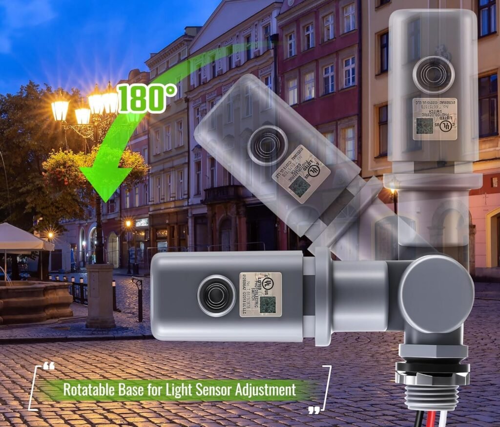
For Twist-Lock (NEMA) Sensors (e.g., LT134, LT154)
In commercial and municipal outdoor lighting twist-lock photocells are common because of their ease of installation and maintenance. These models fit into a standardized NEMA socket.
Key benefits of twist-lock models:
- Quick installation, no wire cutting or stripping
- Easy replacement without tools
- Compatible with standard 3-pin, 5-pin, or 7-pin NEMA receptacles
Pin Functions (ANSI C136.10)
| Pin | Function |
| A | Line (Hot) |
| B | Load (Switched Output) |
| C | Neutral |
| D–G | Dimming/Data (7-pin models only) |
- A (Line): Receives incoming power.
- B (Load): Sends power to the light fixture when the photocell triggers ON.
- C (Neutral): Completes the circuit.
- D-G: Used in advanced systems for dimming or data transmission in smart lighting networks.
Lead-Top twist-lock photocells are compatible with ANSI/NEMA sockets and Zhaga Book 18 interfaces, supporting both standard and smart city lighting systems.
A well-installed photocell sensor means your lights will turn on and off at the right times, There are different types of photocell sensors available, Some are wire-in photocells that you connect directly using wires, Others are twist-lock photocells which simply plug into a standard NEMA socket, these are often used for street lights and large outdoor lighting systems because they are easy to install and replace, without problems like flickering or staying on during the day, Using a right photocell sensor brings many benefits as it helps save electricity because your lights will only be on when they’re truly needed.
Twist-Lock Installation
- Ensure the NEMA socket is correctly wired on the pole or fixture. The socket should already have the necessary connections to the power supply and light fixture.
- Align the pins of the twist-lock photocell with the socket.
- Insert and twist the photocell clockwise until it locks securely in place.
- Power up the circuit. Test the photocell by covering it; the light should turn on. Uncover it and verify the light turns off.
Recommended Lead-Top Models
For both standard and advanced outdoor lighting needs, these Lead-Top models offer proven performance:
| Model | Type | Voltage | Features |
| LT124 | Twist-lock | 120–277V | Economical, reliable dusk-to-dawn control |
| LT134 | Twist-lock | 120–277V | 8A LED load, IP66, zero-cross switching |
| LT154 | Twist-lock | 120–277V | 10-year warranty, fail-on mode, heavy-duty |
| LT210 | Wire-in | 120–277V | Compact thermal type, simple wire-in |
These models are designed to meet high standards for durability and precise light control.
Additional Tips
- Never install the sensor facing the light it controls
- Wire-in photocells should be housed inside a junction box or weatherproof enclosure.
- After installation, observe one full dusk-dawn cycle to ensure correct operation.
- If future upgrades are planned, use 7-pin twist-lock models for dimming and data options
- No matter which type you’re using, it’s very important to connect the sensor properly and install it the right way
Although wiring and installing a photocell sensor is a simple task but it can become a critical one if not done right, Whether you select a direct wire-in model or a twist-lock photocell with a NEMA socket, proper installation of photocell make sure your dusk-to-dawn system functions properly. Following the correct wiring diagram and making sure everything is safe will help your lighting system work as it should. By following correct guidelines, you can achieve long-lasting, automated lighting for homes, streets, or commercial properties.
Need More Information?
Need a downloadable wiring PDF, Zhaga pinout diagram, or control cabinet schematic?
Contact us now and we’ll send it right away.
References: