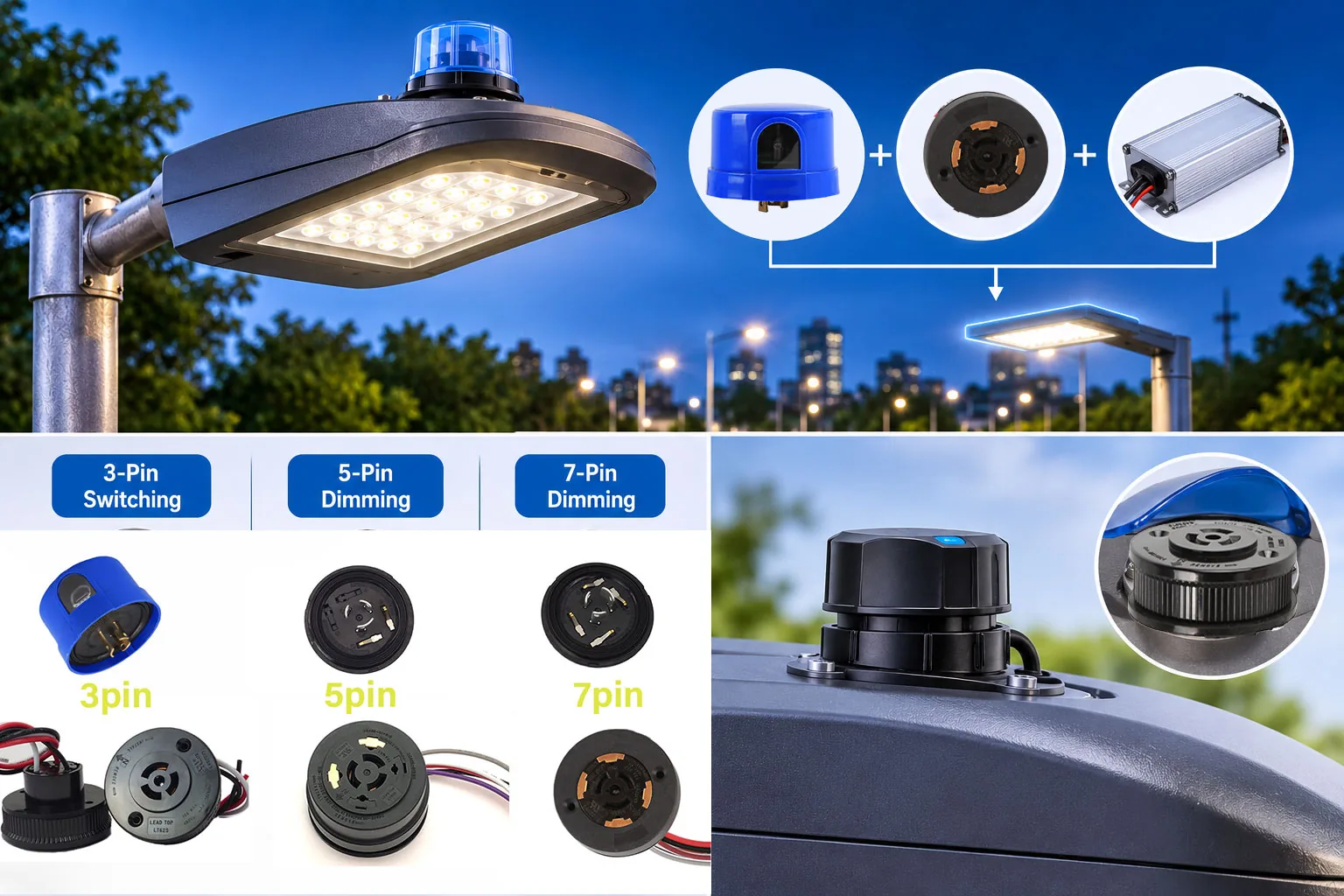
An outdoor lighting control system is not one product. It has three parts:
- A photocell or controller that does the switching
- A receptacle that provides the interface
- A driver that receives both power and control signals
When different suppliers specify these separately, compatibility problems show up after installation, not before.
This guide walks through the four combinations that cover most outdoor lighting programmes:
- Standard 3-pin switching
- 5-pin and 7-pin dimming
- Rotatable interfaces
- Zhaga Book 18
Why Does Light Photocell Sensor and Receptacle Compatibility Matter?
Compatibility has three layers:
| Layer | What must match |
| Electrical | The receptacle’s power contacts (480V / 15A on the NEMA families) must carry the photocell’s rated load. The control’s supply voltage must match the luminaire circuit. Signal pins must match the driver’s dimming input. |
| Mechanical | Both halves must share the interface family: ANSI C136.10 (3-pin switching) ANSI C136.41 (5/7-pin dimming) Zhaga Book 18 (smart nodes) Mounting structure and orientation must fit the housing. |
| Control | On/off versus dimming (0–10V or DALI), and any interface standard the system specifies. |
The system view is simple
Photocell or controller → receptacle → LED luminaire and driver.
The practical rule
The receptacle follows the luminaire. The photocell follows the receptacle. Never the reverse.
How Do Standard 3-Pin Switching Solutions Work?
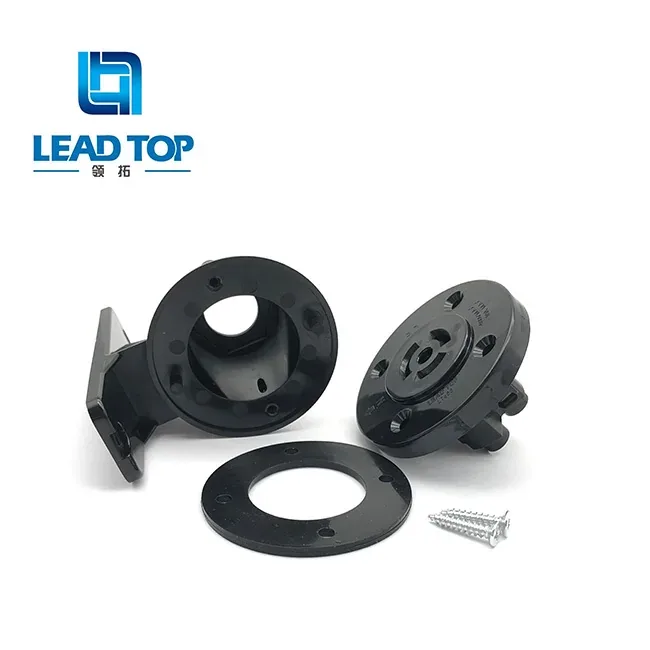
This is the classic dusk-to-dawn package: a 3-pin twist-lock photo switch sensor on a 3-pin NEMA receptacle under ANSI C136.10.
Which receptacles fit?
The LT615 family covers it:
- LT615
- LT625
- LT625R
- LT645
- LT645B
- LT655
They are rated 480V / 480VA, 15A, −40°C to +70°C, with a Bakelite housing.
Which Lighting Control fits where?
| Feature | LT110 series | LT124L |
| Type | Thermal, CDS sensor | Electronic, IR sensor |
| Delay | 30–90 seconds | 2–5 seconds |
| Fail mode | Fail-ON | Fail-ON/OFF configurable |
| Load | Per model | 5A E-Ballast |
| Voltage | 120V / 220V / 208–277V / 480V options | Low limit 90VAC |
| Best for | Slow, drift-tolerant switching | The modern LED default |
The LT124L adds configurable lux, delay, fail mode, and MOV joule options through part-number suffixes.
What should you verify for every pairing?
The interface being standard doesn’t make every pairing right. Check these four points before you finalise a 3-pin light sensor control solution:
- Supply voltage window
- Rated load versus the connected LED load
- Interface family
- Wiring
How Do 5-Pin and 7-Pin Dimming Solutions Work?
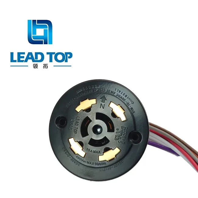
What do the extra pins do?
- 5-pin adds two signal lines for 0–10V dimming.
- 7-pin adds further signal capacity.
- Power contacts stay at 480V / 15A. Signal pins are rated 30V / 0.25A.
So a 3-pin vs 5-pin vs 7-pin choice follows the driver’s control input. It is not a quality ladder.
Which receptacle?
- LT605: fixed
- LT605R: rotatable
- LT635: tool-free 360°
Choose the structure by the luminaire’s orientation needs.
Which control?
Lead-Top’s ANSI C136.41 dimming photocontrol line (120–277V, 5A E-Ballast, 0–10V or DALI, programmable stepped dimming) twists into the same interface.
Why is driver matching the decisive step?
The dimming signal type must match the driver’s control input, either 0–10V or DALI. Ask for the driver datasheet before choosing the control. This is where most combination orders go wrong.
A photocontrol and receptacle can fit together mechanically and still fail to dim the luminaire because the signal type doesn’t match the driver.
Which Rotatable Receptacle Should You Use?
Orientation matters in a combination guide because the control must face the area it senses, and luminaire mounting directions vary across a product range.
- LT605 (fixed)
The simplest option where the mounting direction is known.
- LT605R (rotatable)
- When installing on the light fixture, do not fully tighten the screws yet; you may adjust the orientation as needed before tightening them securely.
- LT635 (tool-free 360°)
Orientation can be adjusted in the field without tools.
For the full structural and installation comparison, see our LT605 vs LT605R vs LT635 guide.
What Does a Zhaga Book 18 Solution Include?
For smart-ready luminaires, the package has two parts:
| Part | Key points |
| LT600 receptacle | Zhaga Book 18, IP66, IK09, PBT housing, aluminium mounting ring, 4-pin (24VDC, DALI−/DALI+ or IO lines), 1.5A / 30V, 10kV insulation to the mounting face |
| LT6001 controller | Lighting controller for 0–10V dimming drivers, 12–24VDC supply |
LT6002 is the DALI-driver variant. Check its current datasheet before specifying.
Two boundaries matter here:
- The 10kV figure is insulation withstand to the mounting face. It is not a surge energy rating, and the two should be kept separate.
- A Zhaga interface is not a network. It is a mechanical and electrical interface. The controller is the sensing and switching layer. The communication platform belongs to the project.
What Mismatches Show Up Most Often?

Most field problems trace back to a handful of avoidable mistakes:
| Mismatch | What happens | How to avoid it |
| 0–10V control on a DALI driver | The luminaire doesn’t dim as expected | Match signal type to the driver’s input |
| Load above the control’s rating | Early failure or nuisance switching | Compare E-Ballast class and driver inrush, not wattage alone |
| Voltage outside the control’s window | Control won’t operate normally | Check the real supply against the voltage range |
| Wrong orientation structure | Sensor faces the wrong way | Pick LT605, LT605R or LT635 to suit the mounting |
Each of these can be caught on paper before anything ships.
How Do You Select a Complete Product Combination?
| Application | Products to consider | Confirm before ordering |
| Standard dusk-to-dawn switching | LT110 or LT124L + LT615-family 3-pin receptacle | Voltage window, load, interface family |
| NEMA dimming (C136.41) | Dimming photocell + LT605 / LT605R / LT635 | 0–10V or DALI, driver input, pin count |
| Orientation adjustment needed | Same control + LT605R (factory) or LT635 (field) | Housing space, rotation range, locking |
| Zhaga smart-ready | LT600 + LT6001 (0–10V) or LT6002 (DALI, verify datasheet) | Book 18 compliance, 24VDC supply, signal lines |
| Wire-in (no receptacle) | LT310A family (120–277V, 2A/5A E-Ballast, optional zero-cross, Fail-ON/OFF) | Wiring length and gauge, mounting position |
The seven confirmations for every combination order
- Luminaire type
- Input voltage
- Rated load
- Control function
- Interface type
- Driver compatibility
- Mounting structure
Which Lead-Top Products Make Up a Dusk-to-Dawn Lighting Control Package?
Lead-Top makes both halves of each combination in this guide:
- Twist-lock photocells: LT110, LT124L, and the LT124 / LT134 / LT154 endurance range
- ANSI C136.10 receptacles: the LT615 family
- ANSI C136.41 dimming receptacles: LT605 / LT605R / LT635
- Zhaga Book 18 package: LT600 with LT6001 / LT6002
- Wire-in controls: the LT310A family
Specifying the set from one factory lets the electrical, mechanical, and control checks be done together.
FAQ
Does a photocell need a receptacle?
No. Locking light sensors will use a receptacle to facilitate removal without tools. Wire-in controls like the LT310A series can be wired into the luminaire without a receptacle. It all depends on whether the programme wants convenience or not.
Can I mix a photocell and receptacle from different suppliers?
A light sensor needs dual compatibility. Electrical and Mechanical. As far as the latter is concerned, ANSI standardization can ensure this. However, the former is ensured only by verifying the pair of components. If you buy both from the same manufacturer, you eliminate this risk.
What is the difference between 3-pin, 5-pin, and 7-pin systems?
- 3-pin carries power for on/off switching (ANSI C136.10)
- 5-pin adds two signal lines for 0–10V dimming
- 7-pin adds further signal lines where the control system specifies them (both ANSI C136.41)
Pin count follows the driver’s control input.
Is a Zhaga Book 18 socket the same as a smart city system?
No, it is not. Zhaga Book 18 specifies the physical interface and the 24V DC power and signal wires between the luminaire and the controller. The network itself is another layer.
What should I send to get a matched combination?
Send the:
- Luminaire type
- Input voltage
- Rated load
- Control function
- Interface type
- Driver model
- Mounting structure
These are the seven confirmations above. With them, Lead-Top can check the electrical, mechanical, and control match in one pass.
Which package fits a 220V 50Hz market?
A 3-pin switching package with the LT110 220V option or a wide-window electronic model. The exact pairing depends on load and interface. Send the luminaire’s voltage and driver details, and Lead-Top will confirm the combination.
The Bottom Line
Reliable outdoor lighting control starts with matching the photocell, receptacle, and driver interfaces as one system. Share your luminaire specifications, interface requirements, and estimated quantity with Lead-Top. The team will recommend a compatible combination and quote the complete package, not just individual components. Lead-Top will confirm the combination.


 English
 Portuguese (Brazil)
 Spanish
 Russian
 Dutch
 Japanese
 Portuguese (Portugal)